Backup Camera Wiring Diagram: How to Connect Each Wire
A backup camera commonly needs four connections: power, ground, video, and reverse trigger; match each wire by function, not color, and the trigger should see reverse only. Wire one wrong and you can get a black screen, rolling video, a dead camera, or a blown fuse. This guide maps each terminal and gives a step-by-step troubleshooting sequence for aftermarket head units and factory-style reverse cameras.
This guide is part of our Backup camera wiring guide for cars and trucks series.
Backup camera wire map
Start with function. The camera needs a stable 12V feed, a low-resistance ground, a composite video path to the display, and a reverse-only trigger path so the head unit knows when to switch. Those jobs are separate, and mixing them causes most faults.
Power wire vs ground wire
The power wire feeds the camera electronics. The ground wire completes that circuit through the chassis or a known ground return. A poor ground can still let a meter read close to 12V with no useful current flow, which is why a camera may power up and still behave badly.
Video signal wire and RCA polarity
The video wire is not a power lead. On most aftermarket installs it lands on an RCA connection that carries single-ended composite video, with a center conductor for signal and an outer shield for return. Connector orientation matters at the head unit input, and splice points are sensitive because extra resistance or a loose shield can corrupt the image.
Reverse trigger wire and head unit input
The reverse trigger wire tells the aftermarket head unit to switch to the camera input. It should see reverse-only voltage, often from the 12V reverse-light source, while the camera itself may be powered from that source or from another fused feed. Do not tie trigger and camera power together unless the diagram for that system says to.
What does each wire do?
Each wire has one job. The camera power wire feeds the camera, the ground wire returns current, the trigger wire wakes the display side, and the video wire carries the image. If you identify those by voltage and destination, wire color becomes secondary.
Camera power source
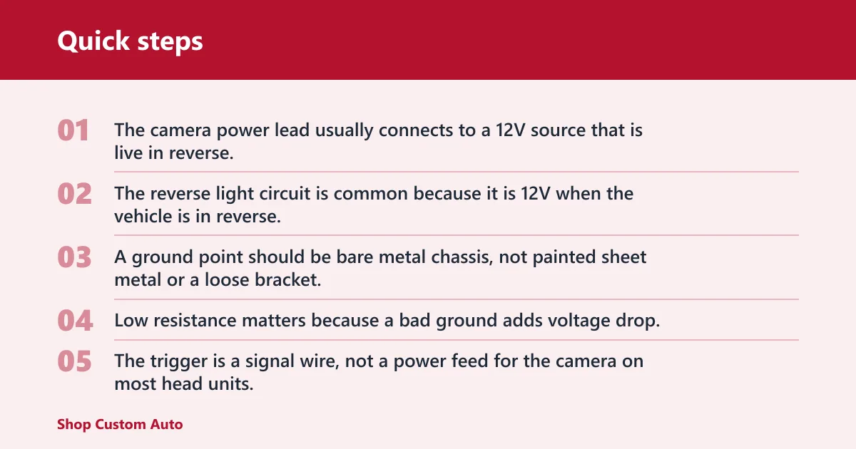
The camera power lead usually connects to a 12V source that is live in reverse, or to a fuse tap or add-a-fuse if you want accessory-safe power. The reverse light circuit is common because it is 12V when the vehicle is in reverse, but it must have a solid ground and enough current margin for the added load.
Ground point function
A ground point should be bare metal chassis, not painted sheet metal or a loose bracket. Low resistance matters because a bad ground adds voltage drop, and that drop can produce intermittent power-up, image noise, or a camera that works only when the hatch or tailgate is closed a certain way.
Trigger signal function
The trigger is a signal wire, not a power feed for the camera on most head units. The aftermarket radio’s reverse trigger lead usually wants a clean 12V reverse signal so display auto-switch behavior happens only in reverse. If the circuit backfeeds, the screen may switch at the wrong time or stay stuck on the camera feed.
Video path to the display
The video path runs from the camera to the head unit camera input, usually through an RCA video input. If the center conductor opens, the shield breaks, or the connector is partially seated, the camera may still have power but the display will stay black, flicker, or show rolling noise.
How do you wire the camera?
Wire the camera in four separate moves: power, ground, video, and trigger. Use the reverse light circuit for power only when you want the camera live in reverse, then send the trigger to the head unit so the display changes at the same time. Keep the video path isolated from both power leads.
Connect power to the reverse light circuit or fused source
Start at the reverse lamp circuit if you want a simple reverse-only feed. If the vehicle’s lamp wiring is thin, shared, or hard to access, a fuse tap or add-a-fuse can give you an accessory-safe power source with fused protection. That is often cleaner than loading the lamp wire directly.
Connect ground to bare metal chassis
Fasten the ground to clean bare metal with secure hardware. Scrape paint if needed. A shared ground with another high-load circuit can create voltage drop, so choose a point that is close, solid, and dedicated when possible.
Run video to the head unit camera input
Route the RCA video cable from the camera to the head unit camera input without sharp bends, crushed sections, or loose adapters. Keep it away from high-current wiring when practical. The cable is more forgiving than a power feed, but splice sensitivity is still real if the shield is interrupted.
Connect the reverse trigger lead
Feed the head unit reverse trigger lead with the same reverse-only signal used to sense gear position, unless the radio manual says to use a dedicated wire at another point. If the radio needs an input and the camera needs a separate supply, keep those paths separate and use a diode or relay where backfeed is possible.
Suppose the camera is mounted at the rear of an SUV and the monitor is in an aftermarket dash unit. If the camera gets 12V in reverse but the screen never auto-switches, that points away from the camera power circuit and toward the trigger lead, the head unit setting, or the RCA path.
Backup camera terminal map
This table gives the terminal-by-terminal view. Read it with a meter, not by color alone.
| Wire or terminal | Function | Expected voltage or state | Where it connects | Most likely failure symptom if miswired |
|---|---|---|---|---|
| Camera power wire | Feeds the camera electronics | 12V in reverse, or fused accessory power if specified | Reverse-light source, fuse tap, or add-a-fuse output | Camera dead, intermittent boot, or fuse opens |
| Camera ground wire | Returns current to chassis | Continuity to bare metal, very low resistance | Bare metal ground point | Black screen, noise, or works only sometimes |
| Video signal wire | Carries composite image | Low-level video, not a 12V feed | RCA video input on the head unit | Power present but no image, rolling picture, snow |
| RCA shield | Video return and noise control | Continuity end to end, no short to center conductor | Outer shell of the RCA path | Interference, flicker, or image loss at bumps |
| Reverse trigger wire | Tells the radio to switch views | 12V only in reverse | Aftermarket head unit reverse trigger lead | No auto-switch, wrong-time switching, stuck camera view |
| Head unit camera input | Accepts the image | Video input only | Dedicated camera input or RCA video input | Camera powers on but display stays blank |
How do you test the wires with a multimeter?
Use the meter in a common order: voltage first, then continuity, then polarity, then signal path. That sequence keeps you from tearing trim apart twice because a simple ground or trigger fault was missed. A good meter reading on the right terminal is more useful than wire color or connector guesswork.
- Set the meter to DC volts and confirm 12V at the reverse-light source with the vehicle in reverse.
- Check the camera power wire for that same 12V at the camera end.
- Switch to continuity and verify the ground wire reaches bare metal chassis with a solid path.
- Confirm the reverse trigger lead sees reverse-only voltage at the head unit.
- Inspect the RCA connection for full seating, correct orientation, and no bent center pin.
- If the image is absent, test continuity through the video cable from end to end and isolate each splice.
Check for 12V in reverse
With the vehicle safely set up and the brake applied, measure the reverse-light circuit in reverse gear. You should see battery voltage only in that state. If the reading appears in park or drive, the wrong wire is being used or a backfeed path exists.
Confirm continuity to ground
Use the continuity check from the camera ground lead to bare metal chassis. A solid ground should read near zero resistance or give the meter’s continuity beep. High resistance here can mimic a bad camera because the unit may power briefly and then fail under load.
Verify polarity and signal path
Confirm the positive lead is on the intended 12V source and the negative lead is truly the return. Then verify the video path separately. A camera can have correct polarity and still fail if the RCA shield is open or the connector shell is not fully seated.
Isolate a bad splice or connector
If the camera works at the source but not at the display, split the circuit in half. Test at the camera end, then at the head unit end, then at any splice. The bad section is usually the one where voltage disappears, continuity opens, or the signal becomes noisy.
Why do power and image fail?
Power and image fail for different reasons, so the symptom tells you where to look. A live camera with no image usually points to the video path, display input, or trigger logic. A dead or unstable camera usually points to power, ground, or a weak reverse-light source.
Camera powers on but shows no image
If the camera has power but the screen stays black, test the RCA cable first, then the head unit camera input. A broken center conductor, damaged shield, or wrong input selection can leave the camera powered and the display blank. A bad splice often shows up only when the cable moves.
No auto-switch to reverse
If the image appears only after manual input selection, the trigger lead is probably missing, on the wrong wire, or getting a weak signal. Some aftermarket head units need a dedicated reverse trigger lead, while others use a camera input sense wire. Check the manual for the exact input type before repinning anything.
Backfeed and trigger problems
Backfeed happens when one circuit sends voltage into another path that should stay separate. That can keep the radio in camera mode, light the wrong lamp, or wake the camera at the wrong time. A diode or relay can block that return path and clean up the trigger signal in complex installs.
Poor ground and voltage drop
Poor grounds create voltage drop that a meter can miss if you only test unloaded voltage. The camera may show a fuzzy image, reset on bumps, or die when the reverse lamps and camera share a weak return path. Recheck the ground point before replacing the camera.
A common first-timer mistake is to tap the reverse lamp wire for everything. That can work on a simple sedan, but on a truck with a long rear wiring run it may leave the camera starved for a clean return path, while the head unit trigger still looks fine.
When should you use a relay or diode?
Use a relay or diode when the reverse signal needs isolation. That matters in mixed-source systems, long runs, or vehicles where the reverse lamp circuit also feeds modules that react badly to added load. The goal is a clean trigger, not a shared path that can backfeed.
Backfeed prevention
A diode prevents current from flowing the wrong direction through a trigger branch. It helps when the camera feed, tail lamp circuit, or head unit sense wire can energize each other. That is a good move when one wire seems to wake multiple circuits.
Clean trigger isolation
A relay lets one small reverse signal control a separate power path. Use it when the camera or accessories draw more than you want the lamp circuit to carry, or when the trigger signal is noisy. The relay keeps the display logic separate from the load side.
Long-run or multi-source installs
Long trucks, trailers, and multiple camera systems often need isolation because voltage drop and shared grounds become more likely. If the reverse signal is split across a bed wiring run, cab wiring run, and aftermarket radio, a diode or relay can keep the trigger from wandering between circuits.
Truck wiring and long cable runs
Truck installs add length, vibration, and routing limits. The longer the run, the more important clean splices, secure grounds, and protected RCA routing become. Cab-to-bed layouts also create more places where a connector can loosen without being obvious at first glance.
Routing through the cab and bed can expose the cable to hinge points, frame movement, and weather where the wiring passes through sheet metal. Splice points add resistance, and the first failures are often in the longest RCA runs or the connector nearest a moving tailgate.
Where extended RCA runs fail first
Extended RCA runs usually fail at the ends and at any mid-run coupler. The center conductor can open, the shield can separate, or the shell can loosen from repeated vibration. If a truck camera works with the cable temporarily rerouted but fails in the final path, the route itself is suspect.
Frequently asked questions
How do I wire a backup camera to reverse lights, ground, and the head unit?
Connect camera power to the reverse-light 12V source or a fused alternative, connect ground to bare metal chassis, run the video cable to the head unit camera input, and feed the reverse trigger lead with reverse-only voltage. Keep power, trigger, and video on separate paths unless the diagram calls for a shared branch.
Which wire goes to the reverse trigger on an aftermarket radio?
The reverse trigger lead on an aftermarket radio goes to a wire that becomes 12V only in reverse, usually from the reverse-light circuit or an equivalent signal source. It should not be tied to the camera’s video lead, and it should not carry the camera’s operating current unless the system manual says otherwise.
What do backup camera wire colors usually mean?
Colors are only hints. Red is often power and black is often ground, but that is not guaranteed across cameras, adapters, or vehicle harnesses. Confirm each wire by voltage, continuity, and destination. The safer rule is simple: identify the function first, then verify the connector or pin label.
How can I tell which wire is power, ground, video, or trigger?
Use a multimeter. Measure 12V on the suspected power lead with the vehicle in reverse, check continuity from the ground lead to bare metal, confirm the trigger lead also sees reverse-only voltage, and inspect the RCA path for intact center conductor and shield. That separates the four functions cleanly.
Why does my backup camera get power but no image?
If the camera has power but no image, the fault is usually in the video path, the head unit input selection, or a bad splice in the RCA cable. A disconnected shield, bent connector pin, or wrong camera input can leave the camera alive and the screen blank. Test the cable before pulling trim again.
Can I extend or splice a backup camera cable without losing signal?
Yes, but only if the splice is clean and the shield stays intact. Composite video is sensitive to poor connections, so every added coupler or twisted splice raises the risk of noise or dropouts. For long truck runs, a continuous cable is usually safer than multiple mid-run repairs.