What Do Backup Camera Wiring Color Codes Usually Mean?
Backup camera wire colors are clues, not rules. Many systems are commonly wired with red for +12V, black for ground, yellow for video, and white or blue for trigger or reverse feed, but every wire should be checked with a multimeter before making a connection. Wrong guesses can pop a fuse, short the camera, or leave the image black. This guide shows the color patterns you’ll see and the exact meter checks for power, ground, video, and trigger wires.
Aftermarket color norms and oem wiring differences
Wire colors usually point you toward a function, but they do not prove it. On many aftermarket kits, red is tied to power or trigger, black is ground, and yellow is the analog video path. OEM-style looms and combo cables often break that pattern, so labels and meter readings matter more than color alone.
Common color cues on aftermarket kits
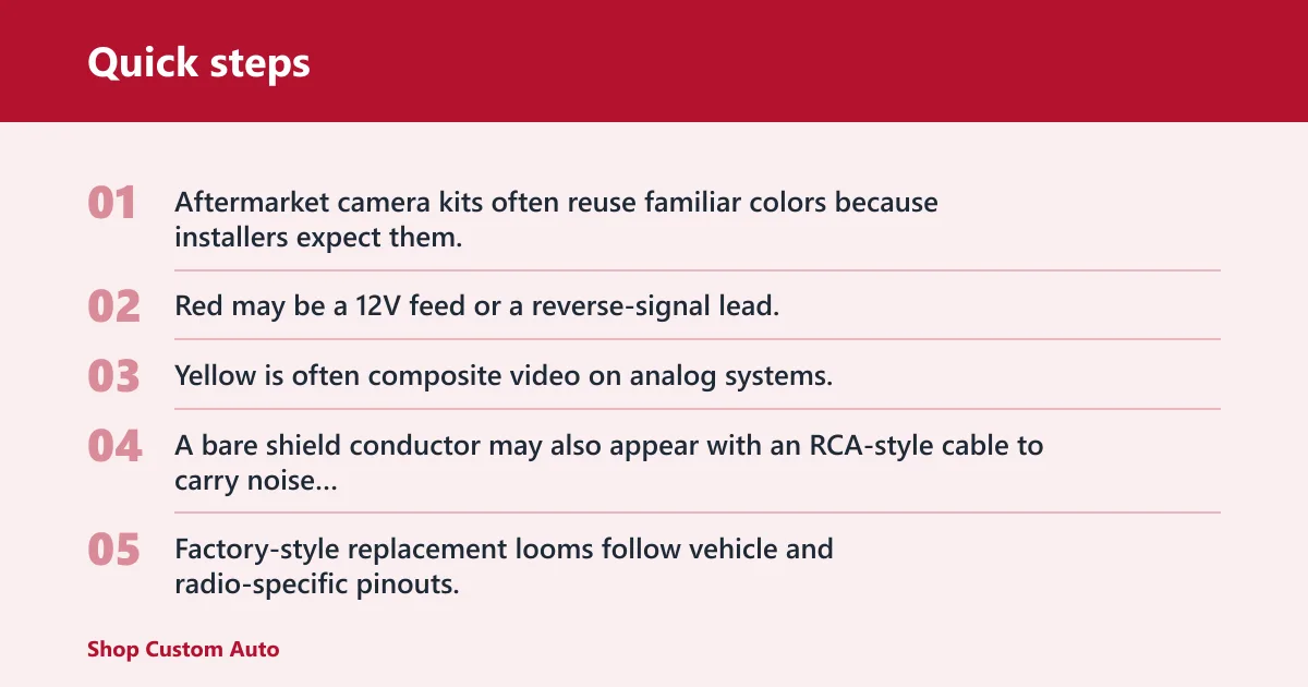
Aftermarket camera kits often reuse familiar colors because installers expect them. Red may be a 12V feed or a reverse-signal lead. Black is commonly ground. Yellow is often composite video on analog systems. A bare shield conductor may also appear with an RCA-style cable to carry noise protection, not power.
Why OEM-style harnesses can differ
Factory-style replacement looms follow vehicle and radio-specific pinouts, not universal color rules. A plug that fits the head unit can still carry camera power on one pin, reverse trigger on another, and video on a shielded pair. In those systems, the connector shape tells you more than the visible insulation color.
When labels matter more than color
Printed labels, molded connector marks, and the wiring diagram beat guesswork every time. Look for terms such as CAM PWR, REVERSE, GND, VIDEO, or SHIELD. If the loom includes small tags, use them first. If tags are missing or translated poorly, confirm each lead with a meter.
Backup camera wiring cheat sheet
| Common color | Likely function | What it is not | How to verify with a multimeter | Common failure signs for aftermarket and OEM-style kits |
|---|---|---|---|---|
| Red | Power or reverse trigger | Not guaranteed video or ground | Measure DC voltage to chassis ground; look for about 12V only in reverse or accessory state | No image, blown fuse, camera powers on only in reverse, display never switches modes |
| Black | Ground | Not a video lead or trigger in most kits | Check continuity to chassis; near 0 ohms to metal ground point | Flicker, rolling noise, intermittent image, camera works only when the loom is moved |
| Yellow | Analog video signal | Not a power wire on standard RCA systems | Inspect RCA center conductor and shield; continuity only in the signal path, no 12V present | Black screen, blue screen, static bars, image cuts out when the cable is bent |
| White | Trigger, signal return, or brand-specific function | Not a reliable universal power lead | Check the manual and meter for voltage or continuity at the labeled pin | Head unit never enters camera mode, image appears only with a manual switch |
| Blue | Reverse trigger or accessory output on some kits | Not always antenna or amp remote in camera kits | Verify when reverse is engaged; confirm whether voltage appears only in that state | Camera turns on at the wrong time, screen stays on camera view after shifting out of reverse |
| Bare shield | Noise shield or drain wire | Not a signal conductor by itself | Check continuity to cable shield and connector shell; it should not show 12V | Noise lines, hum bars, image breaks when other wiring runs nearby |
Is the red wire always power on a backup camera?
No. Red is often power on many kits, but some looms use it for the reverse trigger, a pass-through feed, or a looped accessory connection inside a combo cable. Treat red as a candidate, not a conclusion, and test it against chassis ground before splicing anything.
When red is a power lead
Red is most likely to be power when it shows 12V only in reverse or when the camera is meant to run from accessory power. On a reverse-light-fed setup, the red lead may be tied into the lamp circuit, so the camera wakes only when reverse is selected.
When red is a reverse trigger lead
Some cameras use red to send a reverse signal to the head unit instead of feeding the camera itself. In that setup, the red lead carries a trigger voltage, often 12V in reverse, so the display changes to camera mode. That wire may travel to the radio, not to the camera body.
How combo cables can hide multiple functions
Combo cables can include RCA video plus a thin red wire bonded to the run. That small red conductor may be used as a trigger extension, not camera power. If both ends of the cable have red pigtails, test each end separately so you do not confuse a pass-through wire with a supply lead.
What does the black wire mean on a backup camera?
Black usually points to ground, but it still needs proof. A weak ground can cause no image, flicker, or interference even when the camera powers up. The safest approach is to verify continuity to bare chassis metal and confirm the connection stays solid under vibration.
Finding a solid chassis ground
Use a clean metal point with paint removed, rust cleared, and a tight fastener. A ground bolt near the tail light or cargo area often works better than a random screw in trim. If the meter shows high resistance or unstable readings, pick a different point.
Symptoms of a weak or floating ground
A bad ground often shows up as rolling noise, brief image loss, or a camera that works only when a panel is pressed. If the display wakes but the picture is snowy or black, check the ground first. Many “bad cameras” are only bad grounds.
How do you identify unknown wires with a multimeter?
Use the multimeter to prove voltage, continuity, and polarity before any splice. Check the reverse-light circuit with the vehicle in reverse, confirm which wire is ground, and verify whether the suspect lead changes state under load. Color alone is never enough on a new or unlabeled loom.
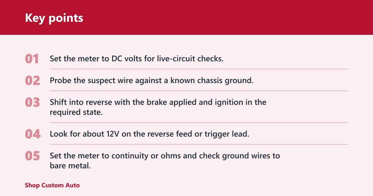
- Set the meter to DC volts for live-circuit checks.
- Probe the suspect wire against a known chassis ground.
- Shift into reverse with the brake applied and ignition in the required state.
- Look for about 12V on the reverse feed or trigger lead.
- Set the meter to continuity or ohms and check ground wires to bare metal.
- Confirm polarity before splicing so the camera’s positive and negative leads match the circuit.
Check voltage in reverse
The reverse light circuit is often used for camera power or trigger. With the vehicle in reverse, a correct feed should usually show battery voltage or close to it. If the reading appears only in reverse, that wire is likely tied to the lamp circuit rather than constant power.
Check continuity to ground
Switch the meter to continuity or low ohms and probe the black lead against chassis metal. A good ground should usually show a very low reading or a continuity beep, depending on the meter. If the number jumps around, the ground point is not stable enough for a camera.
Verify under load, not only at rest
Some wires test fine with no load but fail when the camera is connected. That can happen with thin factory taps, corroded connectors, or a weak reverse-lamp circuit. If a wire reads 12V at rest but the image drops when the camera plugs in, test again with the camera drawing current.
Say your meter shows 12.4V on a reverse feed at the tail lamp, but the screen stays black after you connect the camera. The next check is not another color guess. It is continuity on the ground, then a voltage test again with the camera connected, because a weak splice can collapse under load.
How the reverse trigger and video path work
The reverse trigger tells the head unit or display to switch into camera mode. The video path carries the picture itself, usually on a separate RCA line in analog systems. Keep those jobs distinct. Power turns the camera on, trigger tells the screen when to look, and video carries the image.
Reverse trigger wire at the head unit
Many aftermarket radios have a dedicated reverse input that expects 12V when the shifter goes into reverse. That wire may be labeled BACK, REVERSE, or REAR. If it never sees the trigger voltage, the camera image may be present at the input but never displayed.
RCA video signal on analog systems
On many analog camera kits, yellow RCA usually carries composite video. The center pin carries the signal, and the outer shell acts as shield and return path. Keep that cable away from heavy power runs, because induced noise can add bars, sparkles, or a rolling picture.
Why power and video should stay separate
Do not treat the video cable as a power source. It is built for signal, not current. If you splice 12V into the wrong conductor, the camera or display can fail fast. Separate power, ground, trigger, and video before you make the first crimp or solder joint.
Camera wire guide and multimeter table
Different kit types use different lead patterns. An analog license-plate camera may give you red, black, and yellow. A factory-style replacement may hide those jobs inside a vehicle-specific plug. A pre-wired loom can even add a small red jumper beside the RCA cable for trigger routing.
| Kit or harness type | Common wire pattern | What to verify first | Common failure sign | Quick check |
|---|---|---|---|---|
| Analog aftermarket camera | Red, black, yellow RCA, sometimes bare shield | Power on red, ground on black, video on yellow | Black screen or noisy image | Confirm 12V feed, continuity to ground, and RCA continuity end to end |
| Pre-wired combo cable | RCA with thin red pass-through lead | Whether red is camera power or trigger pass-through | Camera powers but display never switches | Test each red lead separately for voltage in reverse |
| OEM-style replacement loom | Vehicle connector with hidden pin functions | Pinout, ground path, reverse input | Fits the plug but no image appears | Meter each pin at the connector, not just the wire jacket color |
| License-plate camera | Short pigtail, often red and black plus video lead | Solid ground and reverse-fed power | Intermittent picture from hatch movement | Wiggle test the loom while watching voltage and image stability |
What to do if the colors do not match the radio harness
Match functions, not colors. If the radio’s reverse input wants a 12V trigger and the camera kit’s red wire is a supply lead, do not join them just because both are red. Trace each wire from source to destination and verify the pin label or meter reading before you connect.
How to avoid damaging a backup camera when splicing wires
Use the correct polarity, a sound ground, and a splice method that stays tight. Butt connectors, solder joints with heat-shrink, or proper adapter plugs are better than twisting conductors together. Keep the video shield intact, avoid cutting the RCA center conductor too short, and fuse any new 12V feed as close to the source as the kit allows.
Suppose the camera has a red, black, and yellow lead, but the radio loom expects reverse on a blue-white wire and video on RCA only. The safe move is to power the camera from the reverse-light circuit, send a separate trigger to the head unit, and keep the yellow RCA path untouched.
Frequently asked questions
What do backup camera wiring color codes usually mean?
They usually hint at function rather than prove it. Red often points to power or trigger, black to ground, and yellow to video on analog kits. OEM-style and combo looms can use different pinouts, so confirm each lead with a multimeter before any splice.
How do I identify backup camera wires with a multimeter?
Set the meter to DC volts for live checks and continuity for ground checks. Probe the suspect wire against chassis metal, then shift into reverse and look for about 12V on the reverse feed. Confirm the wire’s function before you cut or splice anything.
Can I connect a backup camera without trusting the color code?
Yes, and that is the safer method. Use the connector pinout, the manual, and meter readings to identify power, ground, trigger, and video. Color can help you narrow the options, but the actual voltage and continuity readings should decide the final connection.