
What Color Is the Amp Turn on Wire on a Car Stereo?
The amp turn-on wire is often blue/white, but the reliable match is the lead that shows switched 12V at the head unit and drops to 0V with the key off. Wire it wrong and the amplifier may stay on, drain the battery, or pop on with noise. This guide shows how to identify the remote lead with a multimeter and confirm it before you connect the amp.
Amp turn-on wire basics
The amp turn-on wire, also called the remote turn-on wire, is a low-current 12V trigger. It tells the amplifier when the stereo is on, so the amp powers up with the head unit and shuts down when the head unit turns off. It is not a speaker wire and it is not the main power feed.
On many aftermarket radios, the remote output is blue/white. A solid blue wire often means power antenna instead. That split matters because both wires can appear in the same radio loom, but they do different jobs and are not interchangeable without checking the radio’s wiring diagram.
The amplifier REM terminal expects a small-gauge trigger wire. It does not need high current. It also should not receive speaker-level output directly. If the remote signal is wrong, the amp may never wake up, may stay on all the time, or may turn on with a loud pop.
What color is the amp turn on wire on a car stereo?
Blue/white is common on aftermarket stereos, but it is not universal. Some radios use solid blue for the power antenna lead, and some factory systems use an interface module, not the radio itself, to generate the remote output. The only dependable ID is the wire’s behavior, not its color alone.
Blue/white on many aftermarket radios
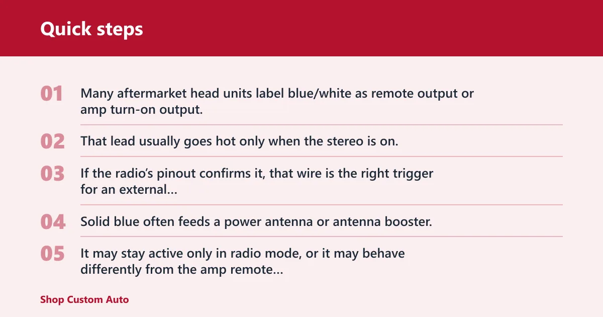
Many aftermarket head units label blue/white as remote output or amp turn-on output. That lead usually goes hot only when the stereo is on. If the radio’s pinout confirms it, that wire is the right trigger for an external amplifier REM terminal.
When solid blue means power antenna instead
Solid blue often feeds a power antenna or antenna booster. It may stay active only in radio mode, or it may behave differently from the amp remote output. Treat solid blue as suspect until the wiring diagram or a meter confirms its function.
Why color alone is not enough
Brand conventions vary, and adapter looms can add another layer of confusion. A blue wire in one radio family may mean remote output; in another, it may not. The safer rule is simple: verify the exact make, model, and trim with the radio wiring diagram or pinout, then test the lead live.
How do you find the remote turn-on wire on an aftermarket radio?
Check the stereo wiring diagram or pinout for the exact radio first, then probe the loom with a multimeter. The correct remote lead should read about 0V with the stereo off and about 12V with it on. That confirms a switched trigger, not a constant feed or speaker line.
Use the wiring diagram or pinout first
Aftermarket radio wire colors vary by brand. The printed pinout or service sheet tells you which terminal is remote output and which one is for the antenna lead. Do not guess from the loom color alone, especially if an adapter loom has already changed the wire colors.
Probe the loom with a multimeter
Set the meter to DC volts and place the black lead on a known ground. Touch the red lead to the suspected remote wire at the back of the radio, at the adapter loom, or at the interface output if one is installed. Turn the stereo off, then on.
Confirm 0V off and about 12V
A good remote lead should sit near 0V when the stereo is off and rise to about 12V when the stereo is on. A reading that stays near 12V all the time usually points to constant power, not a remote trigger. A reading that never rises may mean the wrong wire was probed or the radio does not output a dedicated remote lead.
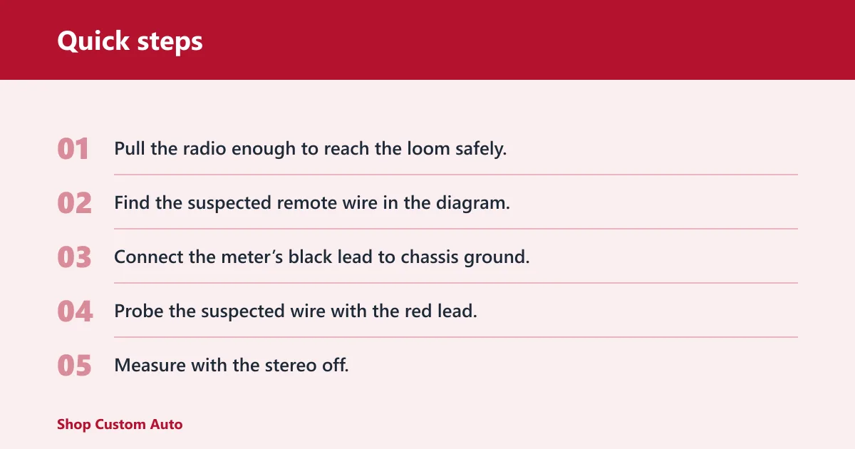
- Pull the radio enough to reach the loom safely.
- Find the suspected remote wire in the diagram.
- Connect the meter’s black lead to chassis ground.
- Probe the suspected wire with the red lead.
- Measure with the stereo off.
- Turn the stereo on and measure again.
- Use only the lead that switches between about 0V and about 12V.
Factory radio remote wire cases
Factory radios often do not provide a simple blue or blue/white remote wire. In many installs, an interface module or LOC with a remote output creates the trigger signal instead. Some factory units offer only accessory-switched 12V, and some offer no dedicated remote lead at all.
When an interface module provides the trigger
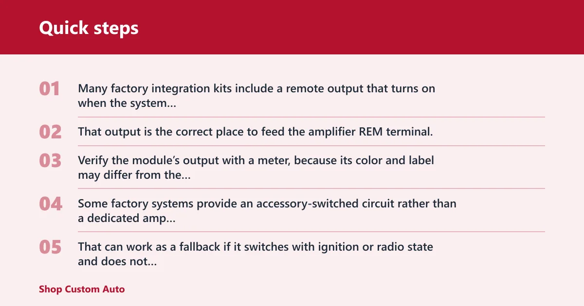
Many factory integration kits include a remote output that turns on when the system wakes up. That output is the correct place to feed the amplifier REM terminal. Verify the module’s output with a meter, because its color and label may differ from the radio’s factory wires.
When the radio only has accessory-switched 12V
Some factory systems provide an accessory-switched circuit rather than a dedicated amp trigger. That can work as a fallback if it switches with ignition or radio state and does not stay live with the key off. It should still be tested before connection.
What to do if there is no dedicated remote lead
If the factory radio has no remote output, the usual fix is an interface module, a LOC with remote out, or a relay triggered by a switched source. The point is to create a clean on-off signal for the amplifier, not to tap a constant feed and hope for the best.
Suppose a factory sedan keeps its amplifier off after a head unit swap. The installer finds a 12V line in the dash, but it stays live with the key removed. That wire is constant power, so it is the wrong choice for REM even though the meter shows voltage.
Remote wire identification checklist
This checklist gives a quick verification path. Use the expected wire color as a clue, not proof. The voltage reading and probe point decide whether the wire is actually the remote turn-on lead.
| Stereo type | Expected wire color | Expected voltage off/on | Where to probe | What failure means |
|---|---|---|---|---|
| Aftermarket radio | Blue/white remote output; solid blue may be antenna lead | About 0V off, about 12V on | Radio loom, adapter loom, or labeled pinout terminal | If it stays at 12V, you found constant power; if it never rises, the wrong lead or wrong radio output was chosen |
| Factory radio with interface | Module output color varies by brand | About 0V off, about 12V on | Interface module remote output or LOC trigger output | If the module output never switches, the interface is not awake, is wired wrong, or is not the correct module for that vehicle |
| Power antenna lead confusion | Often solid blue | May switch only in radio mode or may not match amp trigger behavior | Radio loom at the antenna lead | If the amplifier drops out in non-radio sources, the antenna lead was used instead of a true remote output |
Can you use another wire if the amp remote wire is missing?
Yes, but only if the substitute is a switched source that tracks ignition or radio state. A clean accessory-switched 12V line is the usual fallback. Constant 12V is the wrong choice because it keeps the amplifier awake, which can drain the battery and create turn-on noise.
A common first-timer mistake is tying the amp REM terminal to a fat power wire because it is easy to reach. That wire may measure 12V, but if it never turns off, the amplifier never sleeps. The result is a battery draw that looks like a wiring fault because it is one.
If the trigger is missing or too low, the amp may click briefly and shut back off, or it may never come on at all. Low-voltage triggers are worth checking with the meter before the amplifier is blamed. A weak interface output can act like a bad amp.
Picture a small hatchback with a new head unit and a four-channel amp. The remote wire is tied into a constant fuse by mistake, so the amp stays warm after the key is removed. Swapping that connection to a true switched output fixes the drain, because the amp now turns off with the system.
Will my amplifier turn on without a remote wire?
Usually no. Most amplifiers need a trigger on the REM terminal before they wake up, even if main power and ground are correct. Some amps have signal-sensing or auto-turn-on features, but a standard remote input still needs the right type of signal or an enabled alternate mode.
If an amp has signal-sensing turn-on, follow the manufacturer’s setup instructions. Do not assume that speaker output should be tied into the REM terminal. That is a different circuit and can damage equipment or prevent proper shutoff.
Where does the amp turn-on wire connect on the amplifier side?
It connects to the amplifier’s REM terminal, usually with a small-gauge wire. That terminal accepts a low-current trigger from the head unit, interface module, or approved switched source. It should not receive main battery power and should not be fed with speaker-level output.
Keep the connection clean and short enough to avoid damage or loose contact. If the amplifier has more than one control input, use the one labeled for remote turn-on in the manual. The amp should wake only when the trigger rises to the expected switched voltage.
Frequently asked questions
Is the amp remote wire blue or blue-white?
Blue/white is the more common remote output on many aftermarket radios. Solid blue is frequently used for a power antenna lead instead. Do not treat them as interchangeable; verify the exact radio’s pinout and then test the wire with a multimeter before connecting the amplifier.
How do I test the amp turn-on wire with a multimeter?
Set the meter to DC volts, ground the black lead, and probe the suspected wire with the red lead. Measure with the stereo off and then on. A correct remote wire reads about 0V off and about 12V on.
What voltage should the remote turn-on wire have when the stereo is on?
About 12 volts is the target for a healthy remote trigger. Small variation is normal, but the wire should clearly switch on and off with the stereo or interface module. If it stays near battery voltage all the time, it is likely a constant feed.
What if my factory radio does not have a remote wire?
Use an integration interface, a LOC with remote output, or another switched trigger source approved for the install. Factory wire colors are not universal, so verify the source with a diagram and meter rather than guessing from the loom. That prevents dead batteries and no-turn-on faults.