
What Is an Amp Turn on Wire in a Car Audio System?
An amp turn on wire is a low-current trigger that tells an amplifier to power up, often with a 12V remote signal from the head unit, a relay, or a factory-system interface. If it is missing or wired wrong, the amp stays off, wakes late, or stays on and drains the battery. This article explains where the wire fits in the power-on chain, how to identify the trigger source, and how to troubleshoot wiring versus factory integration problems.
Amp turn-on wire basics
The amp turn on wire, remote turn-on wire, and REM wire are the same control signal in most car audio installs. It is a low-current 12V lead, not the main amplifier power wire, and it tells the amp to wake when the stereo sends its remote signal.
Why the amplifier needs a trigger
An amplifier should not stay awake all the time. The remote signal lets the head unit, factory interface, or relay switch the amp on only when the audio system is active. That cuts battery drain and keeps the amp from powering up with the vehicle parked.
The amplifier remote terminal is usually labeled REM or turn-on. It expects a low-current 12V signal, so a small control wire is normal here. This is not the place for the fused battery feed.
Remote wire vs main power wire
The remote wire is separate from the fused power wire that runs from the battery to the amplifier. The power wire carries the current the amp actually uses. The turn-on wire only sends a signal, so it is usually much smaller, often around 18 AWG.
That size difference matters. If you run a large power cable where a trigger lead belongs, or treat the remote wire like a battery feed, you are solving the wrong problem and may miss the real fault.
Where does the signal come from?
The trigger usually comes from an aftermarket radio, a factory radio integration module, a line output converter with remote output, or a relay. The correct source depends on the vehicle wiring, the radio type, and whether the system is factory or aftermarket.
Aftermarket head unit remote output
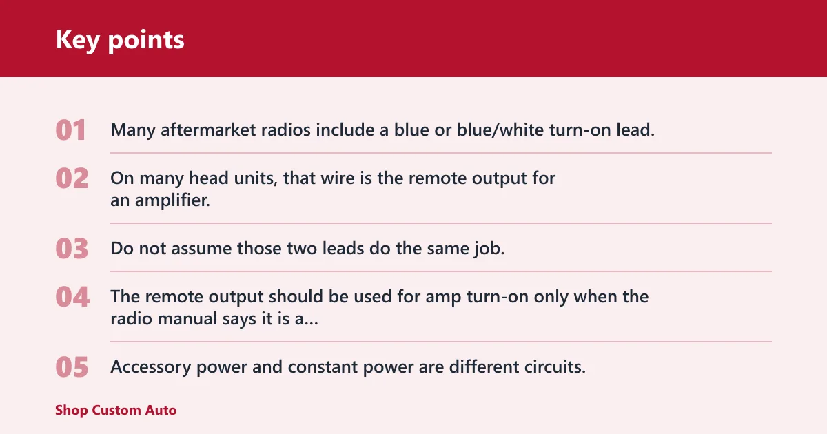
Many aftermarket radios include a blue or blue/white turn-on lead. On many head units, that wire is the remote output for an amplifier, while a separate blue wire may act as an antenna trigger. Do not assume those two leads do the same job.
The remote output should be used for amp turn-on only when the radio manual says it is a remote lead. Accessory power and constant power are different circuits. ACC turns the radio on with the key; constant power keeps memory alive. Neither one should be confused with the amp REM lead.
Factory radio trigger sources
Factory radios vary. Some provide a dedicated amp trigger, some provide only an antenna lead, and many use data-bus control with an integration module. In those vehicles, the amp may never see a simple 12V remote wire from the radio.
Factory amplified systems add another layer. The factory amp may need a wake signal from an interface lead, not from the radio’s speaker wires. A line output converter can also need a remote output or signal-sensing lead, depending on the design.
Antenna trigger vs amp remote output
An antenna trigger may power a mast or amplified antenna, but that does not automatically make it the right lead for an amplifier. Some radios use a blue lead for antenna power and a blue/white lead for amp remote output. Others reverse the function or provide only one trigger.
Read the radio pinout or notes before connecting. If the wrong trigger source is used, the amp may come on late, come on with the key instead of the radio, or never turn on at all.
Amp turn-on wire setup guide
The basic setup is simple: connect the correct trigger source to the amplifier’s REM terminal, then verify that the amp sees about 12V when the audio system is on. The details change when you have multiple amps, a factory system, or an output that cannot supply enough current.
Connect the head unit to the amp REM terminal
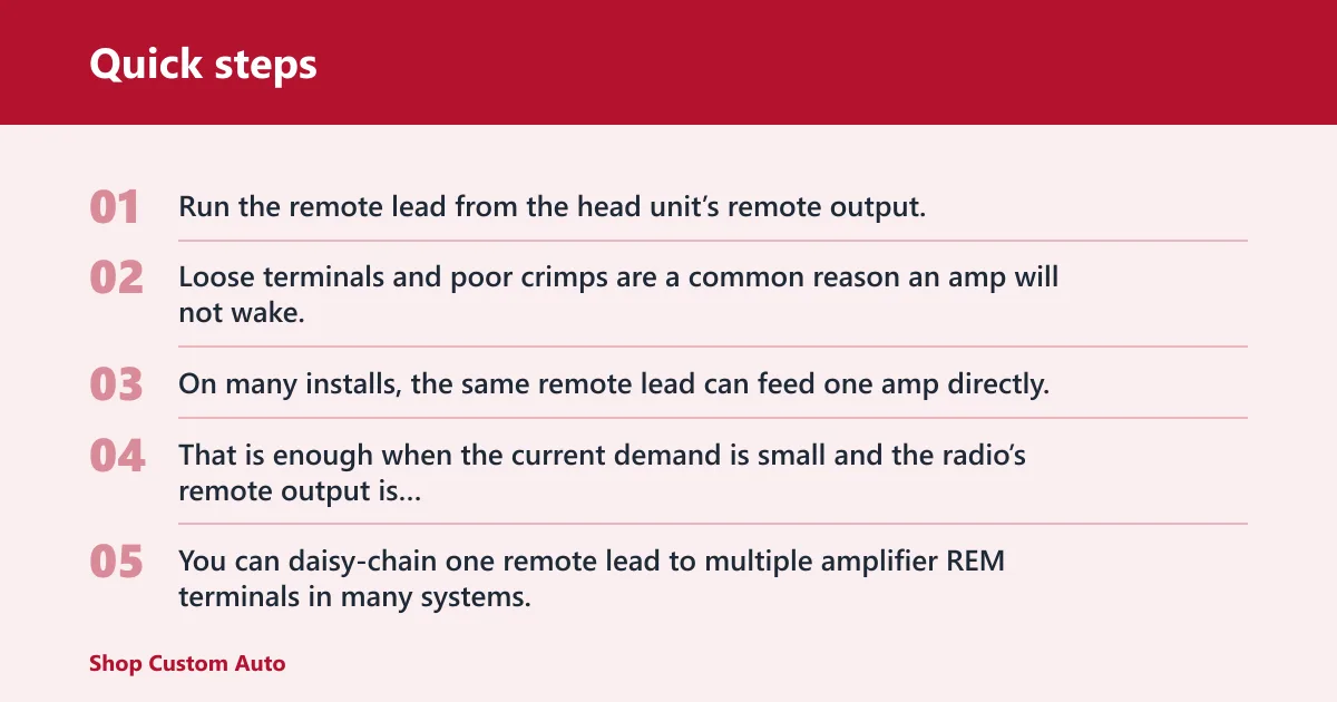
Run the remote lead from the head unit’s remote output, or from the integration module’s remote output, to the amplifier REM terminal. Keep the connection clean and secure. Loose terminals and poor crimps are a common reason an amp will not wake.
On many installs, the same remote lead can feed one amp directly. That is enough when the current demand is small and the radio’s remote output is designed for it.
Daisy-chain multiple amplifiers
You can daisy-chain one remote lead to multiple amplifier REM terminals in many systems, because the turn-on circuit draws very little current. That said, each extra device adds load. If the head unit remote output is weak, or the system includes several amps and a processor, use a relay or an interface output rated for the load.
Picture two amplifiers and a DSP all tied to one factory radio lead. If the lead only delivers a weak trigger, the first amp may click on while the second one stays dead. The fix is usually not a bigger power wire; it is a better trigger path.
When to add a relay
A relay is useful when the remote output current is too low for the system or when the layout calls for isolation. The relay coil uses the small remote signal, and the relay contacts switch a cleaner 12V feed to the amp or to several devices. That protects the source output from overload.
Do not add a relay just because it sounds like a stronger part. Use it when the trigger source cannot carry the combined turn-on load, when a factory interface needs isolation, or when the installer wants one switched feed for several amps.
Wire gauge and fuse placement basics
The turn-on lead is usually a small gauge wire, often around 18 AWG. It carries signal current only, so it does not need to match the fused battery wire size. The fused power wire is a separate main circuit, and its inline fuse belongs near the battery.
Keep the remote wire away from the main power wire in your thinking, even if they share the same route in the vehicle. One feeds the amp; the other tells it when to wake up.
Which turn-on source should I use?
The best source depends on the radio type, the amplifier layout, and whether the vehicle uses factory audio electronics. Match the trigger to the system, then check it with a meter before you blame the amplifier.
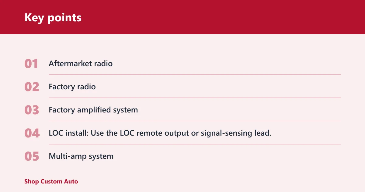
| Setup | Correct trigger source | Adapter or relay | Expected multimeter reading | First test to run |
|---|---|---|---|---|
| Aftermarket radio | Blue/white remote output lead on the head unit | Usually none | About 12V DC with the radio on | Check the radio manual, then probe the remote lead at the harness |
| Factory radio | Integration lead, antenna trigger, or data-bus interface output | Often a vehicle-specific interface | About 12V DC only when the system is active | Verify whether the vehicle has a real amp trigger or only data-bus control |
| Factory amplified system | Factory amp turn-on output from the interface or OEM amp lead | Interface module; relay if the output is weak | About 12V DC at the amp trigger input | Confirm the factory amp is receiving a wake signal before checking speaker outputs |
| LOC install | LOC remote output or signal-sensing turn-on lead | LOC with remote out; relay if current is limited | About 12V DC after audio signal is present, if signal-sensing | Feed audio to the LOC and see whether the remote out appears |
| Multi-amp system | One remote output feeding all REM terminals | Relay if total turn-on load is too high | About 12V DC at each amp REM terminal | Measure the farthest amp REM terminal, not only the first one |
| Relay-needed case | Head unit or interface triggers relay coil; relay feeds the REM line | 12V automotive relay | About 12V DC from relay output to amp | Check coil trigger first, then relay output under load |
Amp turn checklist
Which turn-on source should I use?
- Aftermarket radio: Use the blue/white remote output lead. No adapter is usually needed. Expect about 12V DC when the radio is on. First test: probe the blue/white lead at the harness.
- Factory radio: Use the vehicle’s interface lead or data-bus adapter output. A factory-specific adapter is often required. Expect about 12V DC only when the system is active. First test: verify the interface output before touching the amp.
- Factory amplified system: Use the factory amp trigger from the integration module. A vehicle-specific interface is usually required. Expect about 12V DC at the amplifier wake input. First test: confirm the factory amp wakes before checking speaker signal.
- LOC install: Use the LOC remote output or signal-sensing lead. Some LOCs need an adapter or separate 12V source. Expect about 12V DC after the LOC senses audio, or immediately if it has a hard remote out. First test: play audio and watch the LOC output.
- Multi-amp system: Use one remote lead from the radio or interface to feed all REM terminals. Add a relay if the source output is weak or the load is too high. Expect about 12V DC at each amp REM terminal. First test: measure the last amp in the chain.
- Relay-needed system: Use the radio or interface to trigger the relay coil, then let the relay feed the remote line. The relay is the adapter here. Expect about 12V DC on the relay output. First test: check coil trigger, then output voltage.
How do you test the remote wire?
Use a multimeter in DC voltage mode and test the remote lead with the audio system on. The expected reading is about 12V DC. If you see nothing, or the voltage appears only part of the time, the fault may be the source, the adapter, the relay, or the connection itself.
Multimeter setup for DC voltage
Set the meter to DC volts. Put the black probe on a known good chassis ground and the red probe on the remote wire. Turn the radio on, or turn on the system in the way the vehicle expects, and watch for a stable reading.
If the vehicle uses a factory interface or signal-sensing LOC, test after the source unit is active and sending audio if needed. Some devices do not energize the remote output until they detect a valid wake condition.
Continuity checks and bad-connection clues
If the meter reads voltage at the source but not at the amp, check the run between them. A crimp that looks fine can still be open. A loose set screw at the REM terminal can stop the amp from waking even when the head unit output is correct.
Suppose the head unit shows 12.3V on the blue/white lead, but the amp REM terminal only shows 2V. That points to resistance in the path, a weak splice, or a bad adapter output, not a dead amplifier.
First test when the amp will not turn
- Check fused battery power at the amplifier main terminal.
- Check ground continuity and the amp ground connection.
- Probe the REM terminal for about 12V with the system on.
- Probe the remote source at the radio, interface, or LOC.
- Compare source voltage to amp-terminal voltage to locate the break.
Common turn-on problems
When an amp will not power up, the remote wire is only one part of the check. The real fault may be the wrong trigger source, a blown main fuse, a poor ground, or an overloaded remote output that cannot drive the full system.
Wrong wire choice at the radio
One common mistake is using an antenna trigger when the amp needs a dedicated remote output, or using ACC power instead of a turn-on lead. The result can be delayed wakeup, constant-on behavior, or no turn-on at all.
Blown fuse in the main power circuit
The amp can have a perfect remote signal and still stay dead if the fused power wire is open. Check the inline fuse near the battery and any amp-side fuse before chasing the turn-on lead. A remote wire cannot fix a missing power feed.
Poor ground or loose terminals
A good remote signal does not help if the amplifier ground is bad. Loose terminals, paint under the ground point, or a weak chassis connection can create symptoms that look like a remote problem. Start with the power and ground path, then move to the trigger.
Overloaded remote output
If one head unit output is trying to wake several amplifiers, a DSP, and a factory interface, the source may not provide enough current. That is where a relay or a proper interface output matters. The fix is not a larger remote wire.
Frequently asked questions
What is an amp turn on wire in a car audio system?
An amp turn on wire is the low-current 12V signal that tells the amplifier to wake up. It is also called a remote wire or REM wire. It does not carry speaker power or replace the fused battery feed; it only controls the amp’s on and off state.
Where does the amp remote wire connect on an aftermarket radio?
On many aftermarket radios, the remote wire is the blue/white turn-on lead in the harness. It connects to the amplifier REM terminal, or to a relay coil if the system needs one. The exact lead can vary, so check the radio pinout instead of guessing by color alone.
What voltage should an amp remote turn on wire have?
The remote lead should read roughly 12V DC when the audio system is on. Some systems may show slightly under battery voltage, which is normal. If the reading is near zero, the amp will usually stay off. If it is unstable, look for a bad splice or weak trigger source.
How do I test an amp remote wire with a multimeter?
Set the meter to DC volts, place the black probe on chassis ground, and probe the remote wire with the system on. Read the source first, then the amp REM terminal. If the voltage is present at the source but missing at the amp, the fault is in the run or the connection.
Will an amplifier turn on without a remote wire?
Some amplifiers have signal-sensing or auto-turn-on features, but many do not. A standard amp with a REM terminal needs a trigger signal to power up. If there is no remote wire and no built-in auto-on method, the amp should stay off.
What gauge wire should you use for an amp turn on wire?
A small gauge wire is normal for the remote lead, and 18 AWG is common. The turn-on wire carries signal current only, so it should not be sized like the main power wire. Use the gauge specified by the amp instructions when they call for something different.