
Amp Turn on Wire: What It Is and How to Wire It
The amp turn-on wire is a 12-volt control lead that tells an amplifier to switch on. The radio’s dedicated remote output is commonly the first-choice turn-on source, and a switched 12-volt source or trigger interface is a fallback if that output is missing. Get it wrong, and the amp may stay off, pop through the speakers, pull current with the car parked, or wake up in the wrong key position. This guide shows you how to identify the wire, confirm it with a meter, and choose a safe fallback for aftermarket and factory systems.
The purpose of the remote turn-On wire
Remote turn-on wire versus amp power wire
The amp turn on wire, also called the remote turn-on wire, is a small control circuit. Its job is to send a low-current 12V signal that wakes up an amplifier, powered antenna, DSP, or line output converter with a trigger input.
That is different from the amplifier’s main battery cable. The main power wire carries operating current from the battery through a fused connection. The remote wire does not. If you feed the amp only through the remote terminal, the amplifier will not be powered correctly.
It is also different from constant 12V and from an accessory wire. Constant 12V stays live with the vehicle off. Accessory power usually goes live in ACC or RUN. A proper remote output follows the audio source’s power state, which gives the system a cleaner on-off sequence.
Why the amplifier needs a separate REM terminal
Most car amplifiers have a terminal marked REM, REMOTE, or 12V REM. That terminal tells the amp when to wake and when to sleep. It lets the amp stay off even though the main battery cable is always connected.
This controls two common problems: parked-current draw and bad power-up timing. If the amp stayed awake any time battery power was present, it could keep drawing idle current with the car off. It could also switch on before the radio, DSP, or factory module has stabilized, which often causes turn-on noise or a speaker thump.
Typical voltage and current on a remote trigger
The remote trigger should measure about 12V with the source on and about 0V with it off. If the engine is running, charging voltage may push the reading into the mid-13V or low-14V range, and that is commonly normal.
Current is the part many guides miss. The remote lead is usually meant for a small trigger load, not for powering gear directly. Most manufacturers rate head-unit remote outputs for light current, so one amp is often fine, while several amplifiers and processors may need a relay.
Where does the amp turn on wire connect?
The amp turn-on wire connects from a valid 12V trigger source to the amplifier’s REM, REMOTE, or 12V REM terminal. On an aftermarket radio, that source is usually the blue/white remote output lead. On factory systems, the source is often a line output converter remote output, a signal-sensing interface, or a switched circuit used as a fallback.
At the amplifier
At the amp, the wire lands on the small control terminal marked REM, REMOTE, or 12V REM. It does not go into the large B+ power input, and it does not replace the chassis ground connection.
If the amp has screw terminals, strip only enough insulation for a secure clamp. Loose copper here often causes an intermittent turn-on fault that looks like a dead amplifier.
At an aftermarket radio
The first-choice source is the head unit’s dedicated remote output. On many aftermarket radios, that lead is blue/white and labeled for amplifier remote turn-on. The label matters more than the color.
A solid blue wire is often for a powered antenna on many radios. That wire may only go live in radio mode. If you use it by mistake, the amplifier may shut off when you switch to Bluetooth, USB, or CarPlay.
Say your double-DIN radio has both a blue wire and a blue/white wire. The blue wire powers the antenna lead only in FM mode, while the blue/white wire stays active whenever the radio is on. Pick the wrong one, and the amp seems fine until the source changes.
At a factory system
Factory radios often do not offer a dedicated amp remote lead at the dash. In that case, the cleanest source is usually a line output converter with a remote output, or a signal-sensing adapter that creates a 12V trigger when speaker-level signal appears.
If those are not available, a switched fuse can provide an acceptable trigger source. Use that only as a fallback, because the amp will then turn on with key position rather than with the radio’s own state.
How do you identify the correct turn-on source?
The correct turn-on source is the wire or interface output that shows about 12V only when the radio or trigger device is active, then drops to 0V when it is off. Do not choose by color alone. Confirm the label first, then verify behavior with a multimeter before connecting the amplifier remote terminal.
Aftermarket radio label and color checks
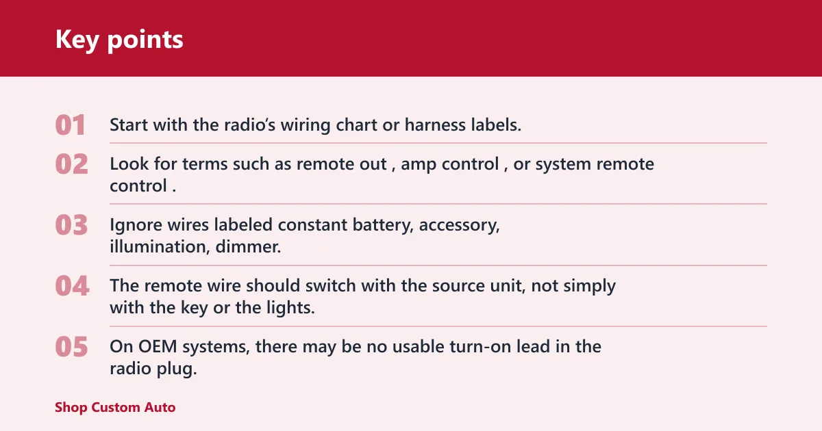
Start with the radio’s wiring chart or harness labels. Look for terms such as remote out, amp control, or system remote control. Blue/white is common, but not universal.
Ignore wires labeled constant battery, accessory, illumination, dimmer, or antenna unless the radio documentation specifically states that they function as the amp remote output. The remote wire should switch with the source unit, not simply with the key or the lights.
Factory radio situations with no remote lead
On OEM systems, there may be no usable turn-on lead in the radio plug. That is why many factory integrations rely on a line output converter with built-in signal detect and remote output. It listens for speaker-level audio, then creates a turn-on signal for the amp.
If the system uses a digital factory amplifier or networked audio module, behavior can change by make and model. Measure the candidate trigger wire with the radio asleep, on, and shutting down, because a wire near the radio may carry data-related voltage, retained accessory power, or another switched signal that looks usable at first glance.
Why accessory, antenna, and illumination wires get confused
Accessory power looks tempting because it switches on and off, but it follows the key, not the audio source. The amp may stay on while the key is in ACC even with the radio muted or asleep.
Illumination and dimmer wires are also switched, but by the light circuit. They are never proper remote leads. Powered-antenna outputs can work only in certain source modes, which creates a hard-to-find symptom.
A common first-timer mistake is tapping the orange illumination lead because it reads voltage with the key on. The amp then turns on only when the parking lights are on, and the real fault looks like a bad amplifier until the meter tells the story.
How to test the wire with a multimeter
Expected readings with the source off
A digital multimeter gives the quickest answer. With the black probe on a known good chassis ground, probe the candidate turn-on source with the red lead.
With the radio or trigger source off, the meter should read 0V or close to it. With the source on, it should read about 12V. In many cars it may read charging voltage when the engine is running, which is normal for a 12V system.
Test at the radio, along the run, and at the amp
- Set the multimeter to DC volts.
- Touch the black probe to bare chassis metal or the amp ground point.
- Probe the radio’s labeled remote wire or the LOC remote output with the red probe.
- Turn the radio off and on, and watch for a change from 0V to about 12V.
- If the reading is correct at the source, test the same wire at the amplifier end.
- If voltage is present at the source but missing at the amp, the problem is in the wire run, splice, crimp, or connector.
What a good reading means and what it does not
A correct voltage reading proves the trigger source is switching, but it does not prove the whole system is healthy. The amplifier still needs a solid ground, proper main battery power, and intact fusing.
Picture a 4-gauge power run with a clean battery fuse and a remote lead that measures 12.4V at the amp terminal. If the chassis ground is loose under paint, the amp still may not wake. Remote voltage alone is only one part of the check.
Can you use an accessory wire instead of a remote wire?
An accessory wire can be used as a fallback trigger if no proper remote output exists, but it changes when the amp turns on. The amplifier will usually wake any time the key is in ACC or RUN, even if the radio is off. Use a true remote output first whenever one is available.
When a switched accessory source is acceptable
An accessory source is acceptable when the amp’s remote input is the only load and the circuit is verified as switched 12V. It can work on basic installs where exact source-based timing does not matter.
This is common on factory-radio systems with no remote lead and no LOC remote output. In that case, a switched fuse tapped with the correct hardware is often the simplest fallback.
What changes when the amp follows the key
Key-triggered turn-on means the amp may power up before the source unit has stable audio output and stay on longer after the source goes quiet. That can increase the chance of turn-on or turn-off noise.
It also means the amp consumes idle current during any time the key remains in ACC or RUN. That is usually manageable for short periods, but it is still less precise than a true radio-controlled trigger.
When to use a fuse tap and when to use a relay
Use a fuse tap on a switched circuit only when a proper remote output is unavailable and the trigger load is small. Match the fuse tap to the panel type, and choose a switched position verified with a meter.
Use a relay when the trigger source is delicate, when more than one amplifier or processor must turn on together, or when the chosen switched circuit should not directly carry all combined remote-input load. A relay lets a small trigger control a separate 12V feed safely.
How to wire factory systems that lack a remote output
LOCs with remote out and signal-sensing adapters
For a factory radio, this is usually the best path after checking for any documented OEM amp-control lead. A good line output converter with remote output watches for speaker-level signal and then sends out a 12V turn-on trigger.
Signal-sensing adapters do a similar job. They are useful when the radio cannot provide a dedicated lead, and they keep the amp from turning on simply because the key is in ACC.
Switched fuse taps as a fallback source
If the LOC or interface has no remote output, a switched fuse can be used. Confirm two things with a multimeter: the slot is dead with the vehicle off, and live in the intended key positions.
The added wire still goes only to the amp’s remote terminal, not to its main power input. Keep the trigger wiring tidy and protected, especially near the fuse panel where moving trim can pinch it.
Relay isolation for OEM circuits and added devices
A relay is a useful middle path when one small trigger needs to switch a cleaner, separate 12V feed for several devices. The source wire energizes the relay coil, and the relay contacts send power to the amp remote leads.
This helps isolate a factory circuit from extra trigger load. It is also a smart move when one signal-sensing output must wake multiple amplifiers, a DSP, and an active crossover.
Turn-on source decision table
Amp turn decision table
| Install scenario | Use this turn-on source | Yes/no path | Tool to verify | Most likely failure point | Troubleshooting note |
|---|---|---|---|---|---|
| Aftermarket radio | Blue/white remote output lead on the head unit | Yes: labeled remote out and switches from 0V to about 12V with radio on. No: do not use solid blue unless the manual says it is remote out. | Multimeter | Wrong radio lead chosen | If the amp works only on AM/FM but not Bluetooth or USB, the antenna lead was likely used instead of the remote output. |
| Factory radio with LOC | LOC remote output or signal-sensing output | Yes: LOC remote terminal produces about 12V when audio signal is present. No: move to switched fuse or relay path. | Multimeter | LOC trigger output not configured or failed | Check LOC settings, power, ground, and speaker-input polarity before blaming the amp. |
| Factory radio without remote output | Switched accessory fuse tap, or relay controlled by a valid switched source | Yes: fuse position is dead with vehicle off and live in ACC or RUN. No: do not use constant battery power except for a brief diagnostic check. | Multimeter and fuse tap | Wrong fuse slot or constant-hot circuit | If the amp stays on with the car off, the chosen fuse is not truly switched. |
| Multiple amplifiers | One remote source feeding a relay, then distributed to all amp REM terminals | Yes: source can trigger the relay coil, and relay output feeds all devices. No: avoid stacking too many remote inputs directly on the head-unit output. | Multimeter and relay | Overloaded head-unit remote output | If one device turns on and others do not, or the radio remote output collapses under load, add a relay. |
| Amp not turning on | Verify the existing source before changing it | Yes: about 12V at amp REM with source on means move to power, ground, fuse, and protect checks. No: trace back to source, splice, LOC, or fuse tap. | Multimeter | Open remote wire, bad crimp, blown remote fuse, or bad ground | Check the remote terminal first, then main B+, ground quality, and amp protect light status. |
Can one remote wire turn on multiple amps?
Yes, one remote wire can turn on multiple amplifiers or processors, but only if the source can handle the combined trigger load. For a single amp, direct wiring is common. For several devices, a relay is the safer distribution method because it keeps the head unit or interface from carrying too much remote current.
Daisy-chaining multiple amplifiers or processors
In a small system, the source remote lead can run to the first amp and then jump to the next REM terminal. Electrically, all those REM terminals are just waiting for a trigger signal.
That does not mean infinite capacity. Each device adds a little load. Two small amplifiers may be fine on one head-unit remote output, but once processors, active crossovers, or a powered antenna join the circuit, caution is wise.
When a relay is the safer method
Use a relay when the source unit remote output is unknown, when the system has several turn-on devices, or when an LOC remote output seems weak or unstable under load. The relay coil draws from the source. The relay output then feeds all REM terminals from a separate fused 12V supply.
That setup also makes troubleshooting easier, because one point controls the whole trigger circuit.
Why your amp is not turning
No trigger voltage at the amp remote terminal
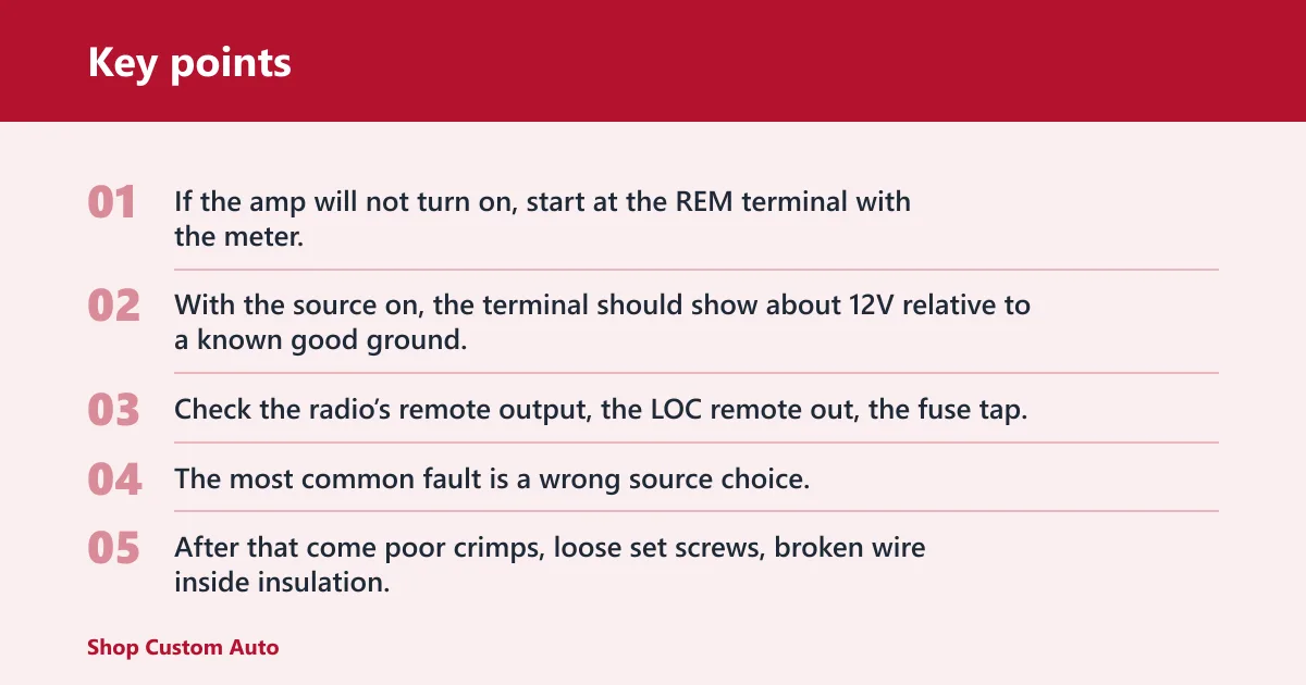
If the amp will not turn on, start at the REM terminal with the meter. With the source on, the terminal should show about 12V relative to a known good ground.
If it does not, the fault is upstream. Check the radio’s remote output, the LOC remote out, the fuse tap, and every splice or butt connector in the run.
Wrong source wire, bad crimp, or open circuit
The most common fault is a wrong source choice, especially blue antenna lead instead of blue/white remote lead on an aftermarket radio. After that come poor crimps, loose set screws, broken wire inside insulation, or an unplugged harness pin.
Suppose the radio shows 12V on the blue/white lead, but the amp terminal reads 0V. That points to the path between them. Recheck each connection in order instead of replacing parts at random.
Ground, fuse, protect mode, and LOC-trigger faults
If the REM terminal does have about 12V, shift to the rest of the amp basics. Check the main battery fuse near the battery, any onboard amp fuses, and the amp’s B+ terminal voltage. Then inspect the ground point for bare metal contact and tight hardware.
If the amplifier enters protect mode, the problem may be speaker wiring, internal fault, low supply voltage, or overheating. If a factory integration uses an LOC, confirm the LOC has power and ground where required, and that its remote output actually switches on under signal.
A brief direct-jumper test from a known switched 12V source to the amp REM terminal can help isolate the remote circuit from the amp itself. Keep it diagnostic only. Do not leave the amp tied to constant battery power, or it can stay on and drain the battery.
Frequently asked questions
What is an amp turn on wire?
An amp turn on wire is the remote control lead that sends a low-current 12V signal to wake an amplifier, powered antenna, or processor. It is separate from the amp’s main battery cable. Its job is control and sequencing, not supplying operating current to the amplifier.
Do I need a remote turn on wire for my amplifier?
Most car amplifiers do need one because the REM terminal tells the amp when to wake up. If the amplifier has signal-sensing auto turn-on built in, a separate remote wire may not be required. If it has a REM terminal and no auto-sense mode, plan on using a trigger source.
What voltage should the remote turn on wire have?
Expect about 12V when the radio or trigger source is on and 0V when it is off. In a running vehicle, the reading can be a bit higher because charging-system voltage rises above battery-at-rest voltage. What matters is the switch from off-state voltage to system voltage, not one exact decimal reading.
What if my amp remote wire is not working?
Check for about 12V at the amp REM terminal with the source on. If voltage is missing, trace back through the source wire, LOC output, fuse tap, splice, and connectors. If voltage is present, inspect the amp ground, main power feed, fuses, and protect status before replacing components.