How to Use a Subwoofer Impedance Calculator
Use a subwoofer impedance calculator to pick a final load that falls inside your amp’s stable range, usually by wiring coils in series or parallel until the total ohms land where the amp can deliver power safely. Get it wrong and you can trigger clipping, protect mode, overheating, or damage to the amp and subs. This guide shows how to read the calculator, compare coil and wiring options, and pick the right series-parallel layout before you buy or wire anything.
What does the calculator tell you?

A subwoofer impedance calculator takes the number of subwoofers and the impedance of each voice coil in ohms, then returns the final nominal load. The calculator can handle subs wired in series, parallel, or mixed layouts, and it usually gives you a wiring path that fits a target amp load. That makes it a planning tool, not a power meter.
Use it to answer one question first: can this sub and amp combination land on a safe load? If the answer is no, stop before you buy parts. If the answer is yes, the next step is choosing the wiring layout that gets you there with the fewest surprises.
What the calculator cannot tell you
It cannot verify the exact behavior of your enclosure, the vehicle electrical system, or the amp’s protection logic. It also cannot replace the amplifier’s stable load rating. The final load still has to stay inside the amp’s safe range, or the amp may shut down, clip early, or fail.
It also does not turn nominal impedance into a fixed real-world number. Impedance changes with frequency, so the calculator’s answer is a planning number, not a constant you will measure at every moment.
How do you enter the right values?
Start with the subwoofer label and the manual. Enter the number of subwoofers, the voice coil count, and each coil’s nominal impedance in ohms. Do not enter a meter reading from a multimeter as the coil rating; that reading is usually DC resistance, not the nominal load the amp sees in use.
Match the sub type before you calculate. A single voice coil sub gives you fewer wiring paths. A dual voice coil subwoofer, or DVC subwoofer, gives you more wiring options because each driver has two coils that can be combined in different ways.
Use nominal ohms, not meter readings
Enter the rated impedance printed by the manufacturer. If the driver is labeled DVC 4 ohm, that usually means each coil is about 4 ohms nominal. The calculator needs those nominal values, not the lower resistance you may see on a meter.
That distinction matters because the calculator is helping you choose a wiring scheme. It is not trying to reproduce a bench measurement of the coil at rest.
How do series, parallel, and series-parallel wiring change the result?
Series wiring adds impedances directly, so the total load rises. Parallel wiring lowers total impedance, which increases current demand. Series-parallel wiring combines both methods and is common when you have multiple subwoofers or multiple coils to balance.
Series wiring
In series, one coil feeds the next. The ohms add. If you have two 4 ohm coils wired in series, the total nominal load becomes 8 ohms. That is a safe load for many amps, but it may leave power on the table if the amp is rated for a lower impedance.
Parallel wiring
In parallel, the amp sees a lower total impedance. That is why parallel wiring is often used when you want the amp to work harder, but it also means the amp must be stable at that lower load. The common rule of thumb is that lower impedance asks more of the amp, but the actual power increase depends on the amplifier’s design, its current limit, the vehicle voltage, and thermal protection. Do not assume a simple doubling effect unless the amp’s manual explicitly supports that operating point.
Series-parallel wiring
Series-parallel wiring is the practical option for multi-sub layouts. You wire matched groups in series first, then parallel the groups. Keep the groups balanced so each side of the layout sees the same load. The speaker impedance calculator page notes that series-parallel wiring can be used for classic four-speaker PA layouts, and the same logic applies to many car-audio sub layouts.
Say your amp is comfortable at 2 ohms and you have two DVC 4 ohm subs. A clean series-parallel layout can land on 2 ohms without forcing the amp below its stable load. The key is to plan the coil groups first, then check the final result before any wire is cut.
What result should you aim for?
Aim for the amplifier’s stable load, not the lowest number you can reach. Many car-audio amps are rated at 4 ohms, 2 ohms, or 1 ohm, and going below the rating risks shutdown or failure. Manufacturer manuals consistently treat the rated load as a hard safety boundary, not a suggestion.
Higher-than-target impedance is usually not a safety problem. It is mainly a power tradeoff. The amp will usually make less output than it would at a lower safe load, but that is different from an unsafe condition.
When a higher load is fine
If your amp is stable at 2 ohms and your calculator lands at 4 ohms, the setup is usually safe. It may simply produce less power than a 2 ohm layout. That can still be the right choice if you want easier thermal load, less current draw, or a wiring layout that fits your subs better.
When the result lands between two ratings
If the calculator lands between amp ratings, choose the nearest load that stays inside the safe range and does not go below the amp’s minimum. If the load is too low, move up to the next safe wiring option. If it is too high, accept the lower power or reconsider the sub and coil combination.
Which subwoofer wiring layouts hit common final loads?
The table below is a decision aid, not a one-size-fits-all wiring map. It shows common setups, safe calculator inputs, and the final nominal loads you should expect when the layout is wired correctly. Use it to pick the right calculator settings before you connect anything.
| Setup | Amp target load | Calculator settings | Final ohms | Use this when |
|---|---|---|---|---|
| Single DVC 2 ohm | 1 ohm | 1 sub, 2 coils, 2 ohms each; parallel the coils | 1 ohm | You want the lowest safe load from one DVC 2 ohm sub and the amp is 1 ohm stable. |
| Single DVC 2 ohm | 4 ohms | 1 sub, 2 coils, 2 ohms each; series the coils | 4 ohms | You want a gentler load for an amp that is rated higher than 4 ohms or performs best there. |
| Single DVC 4 ohm | 2 ohms | 1 sub, 2 coils, 4 ohms each; parallel the coils | 2 ohms | You want one sub to land on a common mid-load without going below the amp’s safe limit. |
| Single DVC 4 ohm | 8 ohms | 1 sub, 2 coils, 4 ohms each; series the coils | 8 ohms | You want a very safe load or you are testing layout options before choosing a stronger amp. |
| Two DVC 2 ohm | 2 ohms | 2 subs, 2 coils, 2 ohms each; series each sub, then parallel the two subs | 2 ohms | You need a balanced two-sub layout that reaches 2 ohms without overloading the amp. |
| Two DVC 4 ohm | 4 ohms | 2 subs, 2 coils, 4 ohms each; parallel each sub, then series the two subs | 4 ohms | You want a 4 ohm final load with two DVC 4 ohm subs and a simple, balanced path. |
| Mixed series-parallel example | 2 ohms | 2 subs, one DVC 2 ohm and one DVC 4 ohm; only use if the calculator shows a balanced valid path | Varies by layout | You are matching mixed-ohm drivers and must confirm the exact final load before wiring. |
| Mixed series-parallel example | Depends on amp rating | 4 subs, matched coils, series groups first, then parallel the groups | Varies by layout | You have a multi-sub install and need the calculator to verify a balanced series-parallel path. |
The mixed rows are intentional. They show the point where the calculator matters most: mixed-ohm systems can look close on paper but land in the wrong place if you guess. Do not force a layout that the calculator cannot support cleanly.
How do DVC subs change the math?
DVC subs give you two coils per driver, which means more wiring choices and more chances to hit an exact target load. A DVC 4 ohm sub can wire to 2 ohms or 8 ohms, depending on whether you use parallel or series wiring. The same logic applies to many other DVC values.
That flexibility helps when you are trying to match a specific amp rating. It also means you need to confirm which coil is which before you wire anything, because a misread DVC layout can send the calculator in the wrong direction.
Common final loads you can target
For many car-audio setups, 1 ohm, 2 ohms, and 4 ohms are the loads people try to hit on purpose. Those are common amp ratings, so they are practical targets. If you only remember one rule, make it this: pick the load the amp can handle cleanly, not the one that sounds most aggressive on paper.
What is the difference between nominal impedance and real impedance?
Nominal impedance is the rated value, measured in ohms, that you use for planning and wiring. Real impedance changes with frequency, so the number is not constant in actual playback. IEC loudspeaker standards and manufacturer manuals both treat nominal impedance as a rating class, not a fixed operating point.
That is why a multimeter reading can look lower than the label. The meter is reading DC resistance, while the amp sees a frequency-dependent load that moves around during music playback.
Why a multimeter shows DC resistance
A meter measures the coil at rest. It does not reproduce the changing AC signal from the amplifier. So a “4 ohm” sub may measure below 4 ohms on a meter and still be a 4 ohm nominal driver. That difference is normal.
Picture a 4 ohm DVC sub that reads a little under 4 ohms on a meter. That does not mean the sub is mislabeled. It means the meter is measuring something different from the calculator input, which is why the nominal rating is the correct one to enter.
What impedance dips can mean for the amp
Real impedance can dip below nominal, so the amp may see a harder load at some frequencies than the calculator’s final number suggests. That is one reason stable-load headroom matters. Loudspeaker standards such as IEC 60268-5 allow nominal-rated speakers to vary around the label, which is exactly why amplifier manuals stress minimum safe load ratings.
How do I measure subwoofer impedance?
Use a digital multimeter to check DC resistance at the speaker terminals, not to determine the sub’s nominal impedance. The reading helps confirm coil continuity and identify open or shorted coils, but it should not replace the manufacturer’s rated ohms when you enter values into a calculator.
Set up the meter correctly
Turn the amplifier off and disconnect the subwoofer from the amp or crossover so the meter only sees the driver. Set the multimeter to the lowest resistance range or auto-ranging ohms mode. Touch one probe to each terminal of the voice coil you want to test, and wait for the reading to settle.
Where to probe on single-coil and DVC subs
On a single voice coil sub, probe the positive and negative terminals of that coil. On a DVC sub, probe one coil at a time, then repeat on the second coil. If the sub has separate terminal pairs for each coil, test each pair independently so the readings stay clear.
What readings to expect
A healthy coil usually reads below its nominal rating because the meter measures DC resistance, not AC impedance. For example, a nominal 4 ohm coil often measures somewhat under 4 ohms at rest. The exact reading depends on the driver, meter accuracy, and ambient temperature, so the important question is continuity and consistency, not an exact printed value.
What suggests an open or shorted coil
A reading that stays at or near infinity or OL usually suggests an open coil, broken lead, or disconnected path. A reading that is extremely close to 0 ohms can indicate a shorted coil or a wiring fault. If one coil in a DVC sub reads normally and the other does not, the faulty coil may be the source of the problem.
How do I know if my amp can handle the final subwoofer load?
Check the amplifier’s minimum safe impedance rating and compare it with the calculator result. If the final load is at or above the amp’s stable load, the wiring path is usually acceptable. If it falls below the rating, do not wire it that way. Going below the amp’s safe range risks shutdown or failure.
Correct wiring is only part of the picture. Amp manuals also tie safe operation to speaker load, ventilation, and power supply quality, so the wiring decision should always stay inside the product’s published limits.
How to handle protect mode or weak output
If the amp goes into protect mode, the load may be too low, the wiring may be wrong, or the system may have a power problem. If output is weak, the load may be higher than the amp’s best operating point, or the subs may be wired in a way that splits power unevenly. Recheck the calculator inputs before changing anything else.
- Confirm the sub count and each coil’s nominal ohms.
- Choose the series, parallel, or series-parallel path that matches the target load.
- Compare the final load with the amp’s stable load rating.
- Verify the wiring diagram before connecting the amp.
- Follow the vehicle and product manual for all electrical work.
How do I calculate DVC subwoofer impedance?
Start by treating each voice coil as its own impedance source, then combine the coils in series or parallel to make one driver load. After that, combine multiple drivers with series, parallel, or series-parallel wiring until the calculator shows the final nominal load. That is the cleanest way to handle a DVC setup.
For a single DVC sub, the math is simple. For two or more DVC subs, build the system in stages. First make equal sub groups. Then combine those groups. Balanced groups matter because uneven group wiring can give you a result that looks close but is not correct in practice.
What are the most common subwoofer impedance questions?
These are the questions that usually decide whether a build works safely: how to use the calculator, what ohms to enter, how series and parallel change the load, how to compare nominal and real impedance, and how to confirm the amp can handle the result. The answers below keep those checks in one place.
How do I use a subwoofer impedance calculator?
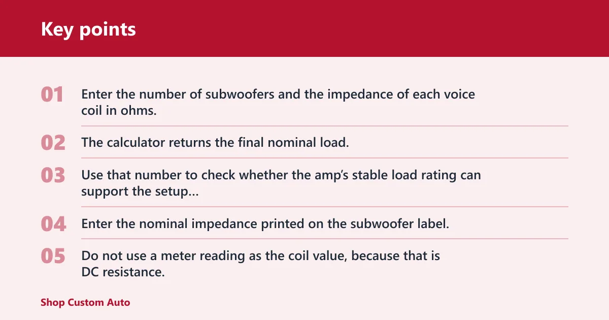
Enter the number of subwoofers and the impedance of each voice coil in ohms, then choose series, parallel, or series-parallel wiring. The calculator returns the final nominal load. Use that number to check whether the amp’s stable load rating can support the setup before you buy parts or wire the system.
What ohms do I enter in a subwoofer impedance calculator?
Enter the nominal impedance printed on the subwoofer label, such as 2 ohms or 4 ohms per coil. Do not use a meter reading as the coil value, because that is DC resistance, not the rated load. If the sub is DVC, enter each coil separately.
How do series and parallel wiring change subwoofer impedance?
Series wiring adds the impedance values together, so the total rises. Parallel wiring lowers the total impedance, which increases current demand from the amp. Series-parallel wiring combines both methods and is common in multi-sub layouts where you need to hit a specific final load.
What is the difference between nominal impedance and real impedance?
Nominal impedance is the rated load used for wiring decisions. Real impedance changes with frequency, so the actual load can move during playback and may dip below the nominal value. That is why a 4 ohm sub can measure lower on a meter and still be a 4 ohm driver.
How do I know if my amp can handle the final subwoofer load?
Compare the calculator result with the amplifier’s minimum safe impedance rating. If the final load is at or above that rating, the wiring is usually acceptable. If it goes below the rating, choose a different series or parallel path. Lower than rated can overheat the amp or trigger protect mode.
Why does my 4-ohm sub show a lower reading on a meter?
A meter reads DC resistance at rest, not nominal impedance under signal. Because impedance changes with frequency, the measured value is often lower than the printed rating. That difference is expected, so use the nominal value for the calculator and the meter only as a basic check of continuity.
Which internal guides help with safe subwoofer wiring?
When the final load is close, the best next step is to confirm the amp’s stable operating range, compare wiring topologies, and check power matching. These related guides help with those decisions:
mono amp stable load, series vs parallel speaker wiring, RMS power matching, and subwoofer wiring diagrams.
Sources
- IEC 60268-5, Sound system equipment — Part 5: Loudspeakers.
- JL Audio amplifier manuals: minimum speaker impedance, wiring cautions, and safe operating limits.
- Rockford Fosgate amplifier manuals: stable load ratings and wiring guidance.
- Alpine amplifier manuals: speaker load specifications and protect-mode behavior.
- Manufacturer subwoofer manuals and spec sheets: nominal impedance, DVC configuration, and coil labeling.