How to Test Backup Camera Wiring with a Multimeter
Test backup camera wiring with a multimeter by checking 12-volt power first, then ground continuity, then the video or trigger signal path, and stop at the first failed reading. Skip that order, and you can waste time replacing a good camera, screen, or section of wiring. This guide shows a three-stage workflow so you can isolate the exact bad wire or connection.
What you’ll need
- Multimeter with voltage mode, continuity mode, and ohms resistance mode
- Test leads in the COM and VΩ ports
- Auto-ranging meter, or a manual-range meter set correctly
- Electrical contact cleaner
- Heat shrink tubing or heat-shrink connectors
- Wire strippers and crimp tool, if splicing is needed
- Needle probes or back-probe pins for connector testing
- Electrical tape only as a temporary wrap, not the final repair
Set the black lead in COM and the red lead in VΩ before you start. Use DC volts for live power checks, continuity for open-circuit checks, and ohms when you need a resistance reading on an unpowered wire. If your meter is manual-range, choose the next range above the expected value.
How do you test backup camera wiring with a multimeter?
Start with power at the rear camera, then ground, then the video path. Most backup cameras draw power from the reverse-light circuit, so the camera should typically see about 12V only when reverse is selected. If power and ground pass, move to the video cable and connector path before replacing the camera.
Check the reverse-light circuit first
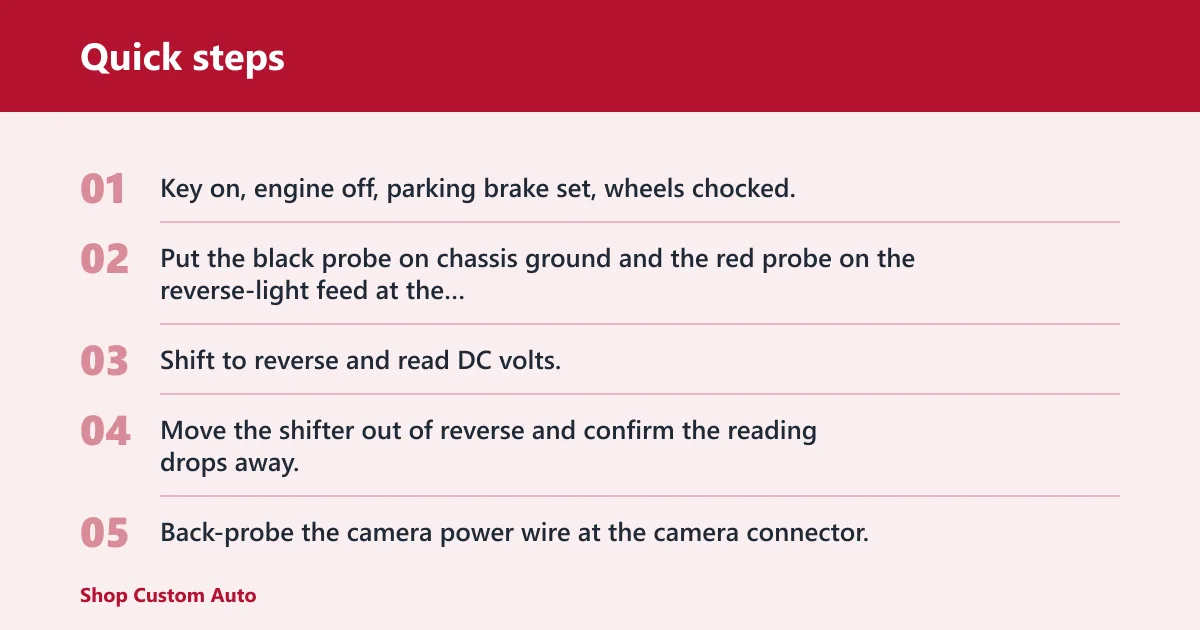
- Key on, engine off, parking brake set, wheels chocked.
- Put the black probe on chassis ground and the red probe on the reverse-light feed at the trunk or tailgate access point.
- Shift to reverse and read DC volts.
- Move the shifter out of reverse and confirm the reading drops away.
A healthy circuit usually reads about 12V in reverse and near 0V outside reverse. If the meter shows voltage only sometimes, suspect an intermittent reverse trigger, a loose splice, or a connector that opens under vibration.
Confirm 12V at the rear camera
- Back-probe the camera power wire at the camera connector.
- Keep the black lead on a known-good chassis ground.
- Select reverse and check for 12V at the camera side, not only at the source wire.
- Compare the reading at the source and at the camera to find voltage loss in the run.
If the source has 12V and the camera does not, the fault sits between them. A broken conductor, corroded splice, or damaged connector is more likely than a bad camera.
Find intermittent power faults
Suppose the camera works in one gear position but cuts out when the tailgate closes. That points to a wire that opens when flexed, often near a hinge or connector. Keep the meter on the camera power wire, then gently move the wiring and watch for a drop.
Voltage that appears only when the circuit is unloaded can fool a quick check. If possible, test with the camera connected so the wire is carrying current, not just showing a floating reading.
How do you test backup camera ground with a multimeter?
Test the ground with a voltage drop check first, then a resistance check if the circuit is off. A bad ground can mimic a dead camera, a dim image, or a screen that cuts out under load. Corrosion and loose fasteners are common failure points on chassis ground connections.
Use a voltage drop check
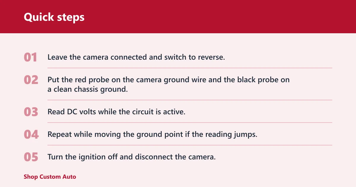
- Leave the camera connected and switch to reverse.
- Put the red probe on the camera ground wire and the black probe on a clean chassis ground.
- Read DC volts while the circuit is active.
- Repeat while moving the ground point if the reading jumps.
Low drop is the goal. If the meter shows a noticeable voltage on the ground side while the camera is running, the return path has resistance. Clean the ring terminal with contact cleaner, remove oxidation from the contact point, and retest.
Check chassis ground resistance
- Turn the ignition off and disconnect the camera.
- Set the meter to ohms or continuity mode.
- Probe the camera ground pin and a known chassis ground point.
- Look for a low reading or a beep, then wiggle the connector.
High resistance or an open circuit means the ground path is bad. If continuity comes and goes while you move the wiring, the ground may be loose inside the connector or corroded at the crimp.
Spot corrosion and loose grounds
A loose ground often causes symptoms that change with tailgate movement, body flex, or wet weather. Clean the connection with contact cleaner, let it dry, then retest. If the terminal is green, pitted, or loose, repair the end rather than trusting the old crimp.
How do you test the video wire?
Test the video cable separately from power so you do not blame the wrong section. Aftermarket systems often use an RCA video line, while others use a 4-pin aviation connector or a factory/OEM wiring run. A connector can look fine and still fail continuity or shield integrity, especially if the screen flickers when the cable moves.
Test RCA continuity
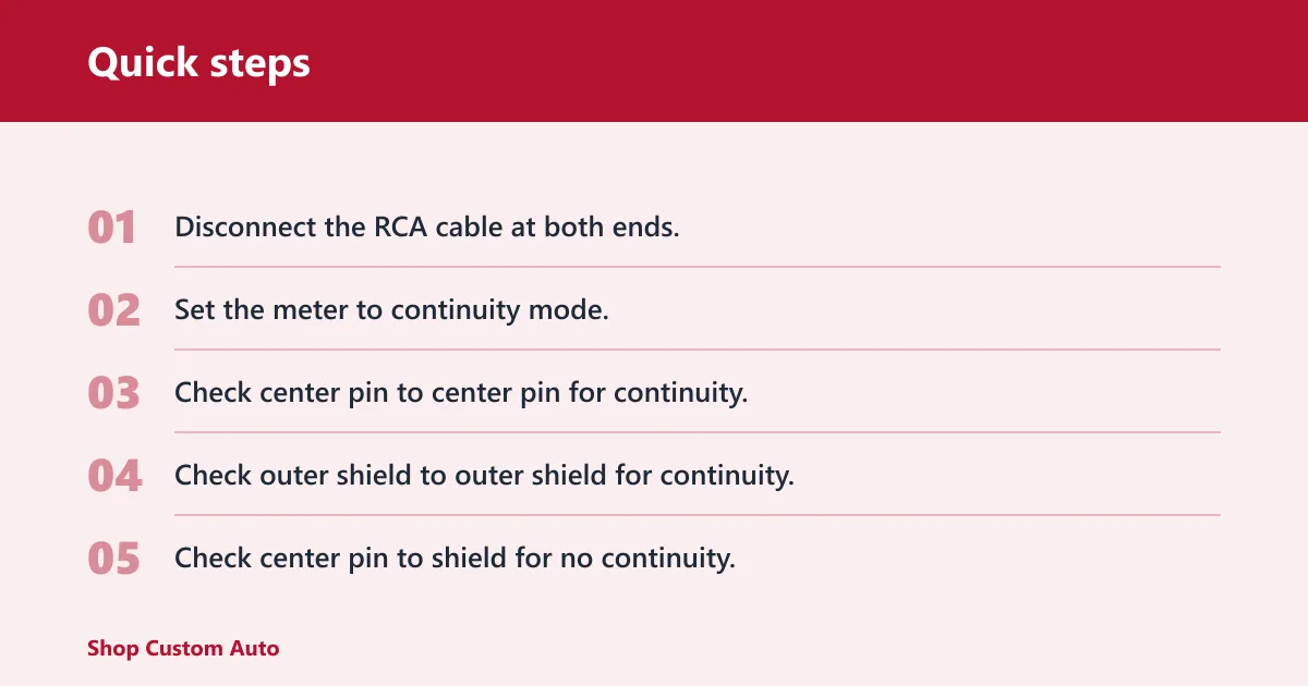
- Disconnect the RCA cable at both ends.
- Set the meter to continuity mode.
- Check center pin to center pin for continuity.
- Check outer shield to outer shield for continuity.
- Check center pin to shield for no continuity.
If center-to-center passes but the image cuts out, inspect the shield and connector retention. A broken shield can still let the wire “pass” a simple check while the picture flickers.
Test 4-pin connectors
- Identify each pin by pinout, not color alone.
- Probe pin to matching pin with the meter in continuity mode.
- Check for shorts between adjacent pins.
- Inspect for bent pins, pushed-back pins, or cracked housings.
4-pin aviation connectors depend on pin alignment and shell retention. If the image returns when you press the connector together, the latch or pin tension is suspect even if the wire tests okay on the bench.
Test factory/OEM harnesses
- Find the rear camera signal path in the factory wiring.
- Back-probe at the rear connector and at the head unit connector.
- Check continuity from end to end with the circuit disconnected.
- Check for no continuity to power or ground on adjacent pins.
Factory systems may receive a reverse signal from the transmission range switch, body control module, or infotainment system. That means you may be testing a trigger wire, a video wire, or both. Verify each pin before assuming the same color means the same job.
Run a wiggle test
- Keep the meter on the suspect wire or connector.
- Flex the wiring at the camera end, midpoint, and head unit end.
- Watch for a reading that opens, spikes, or drops out.
- Mark the spot where movement changes the meter result.
Why does the backup camera work only when you move the cable? Because a broken conductor, loose pin, or damaged shield can make contact only in one position. That points to the exact section that needs repair.
Backup camera diagnostic table
Use this worksheet at the rear camera, midpoint, and head unit. Enter the actual reading before you replace anything. A clean pass at one point and a fail at the next tells you where the fault starts.
| Test point | Meter setting | Expected reading | Actual reading | Likely fault |
|---|---|---|---|---|
| Rear camera power wire | DC volts | About 12V only in reverse | Missing reverse feed, blown splice, bad trigger wire | |
| Rear camera ground wire | Voltage drop | Low drop to chassis ground | Corrosion, loose ground, paint under terminal | |
| Rear camera ground wire | Ohms or continuity | Low resistance or beep to chassis ground | Open ground, broken crimp, poor chassis bond | |
| RCA video line, center pin to center pin | Continuity | Beep or low resistance | Open center conductor | |
| RCA video line, shield to shield | Continuity | Beep or low resistance | Broken shield, poor connector crimp | |
| 4-pin connector, matching pin to matching pin | Continuity | Beep or low resistance | Bent pin, pushed-back terminal, cracked shell | |
| Factory wiring at rear and head unit | Continuity and wiggle test | Stable reading while moved gently | Intermittent conductor, damaged splice, loose terminal |
Common mistakes
Borderline readings cause a lot of wrong parts orders. If continuity passes but resistance is higher than expected, the wire may be damaged inside insulation or the terminal may be partially loose. A pass on the meter does not prove the line is healthy under vibration or load.
Do not trust one quick voltage check
- Test at the source and at the camera.
- Compare readings with the circuit loaded, not unplugged only.
- Repeat the test while the wiring is moved.
A common first-timer mistake is finding 12V at the reverse-light wire and stopping there. If the camera still fails, the break is usually farther downstream in the connector, splice, or ground path.
Do not skip connector inspection
- Inspect for corrosion, bent pins, cracked housings, and weak retention.
- Clean metal contacts with electrical contact cleaner.
- Let the connector dry before the next test.
A broken backup camera connector can cause a screen that is flickering, showing no signal, or cutting out intermittently. A multimeter can help confirm whether there is no continuity or missing voltage, but it cannot fix a loose latch or green corrosion.
Do not rely on tape alone
- Strip back to clean copper.
- Join the wires with a proper crimp or soldered splice.
- Seal the repair with heat shrink tubing.
- Retest after the splice cools and before reassembly.
Heat shrink tubing gives better weatherproofing and vibration resistance than tape alone. That matters near a tailgate, trunk lid, or rear bumper where motion and moisture are constant.
Frequently asked questions
How do I check if my backup camera has power in reverse?
Back-probe the camera power wire at the rear connector, place the black lead on chassis ground, and shift to reverse. A healthy circuit should show about 12V only when reverse is selected. If the source shows voltage but the camera end does not, the fault is in the run.
How do I tell if the video wire or power wire is bad?
Check the power wire first at the rear camera. If it has 12V in reverse and the ground checks out, move to the video line. If the picture returns when the cable is moved, focus on the video cable, connector pins, or shield rather than the power feed.
What voltage should a backup camera wire have?
The reverse-triggered camera feed should typically show about 12V when reverse is selected and near 0V otherwise. If the reading appears only with the connector unplugged, or drops when the camera is connected, the circuit may have high resistance or a bad splice.
Can a multimeter confirm a bad connector or splice?
Yes. A continuity test can show an open or a high-resistance path, and a wiggle test can expose a fault that appears only when the connector moves. If cleaning with electrical contact cleaner and drying the connector changes the reading, the connector or splice is a likely failure point.
How do I test the reverse light wire that powers the camera?
Use the meter in DC volts at the trunk or tailgate access point, because that is often where the reverse-light circuit is easiest to reach. Put the black lead on chassis ground, the red lead on the reverse wire, and verify about 12V only in reverse.